
SEVENOAKS
TONBRIDGE
TUNBRIDGE WELLS
ORPINGTON
BROMLEY
DARTFORD
01732 617161
BUILDING SUPPLIES LTD

01689 869090


Box Lintels
Box Steel Lintels
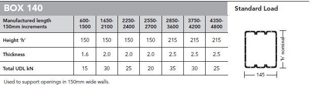
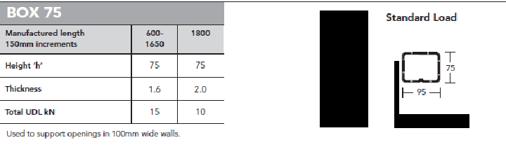
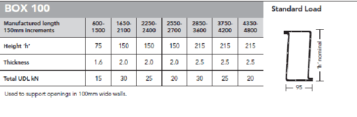
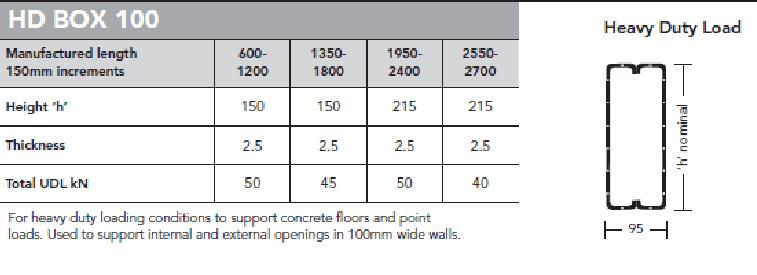
Used to support openings in 100mm wide walls. Steel Lintels may be propped to facilitate speed of construction.
Specification
Technical Information details all the specification clauses required for IG lintels. The Specification Clause required for Box lintels is titled “Other Lintel Applications”.
Installation
Box Lintels must have a minimum end bearing of 150mm on each side of the opening, bedded on mortar. Level the lintel along its length and across its width. Masonry built must be laid on a mortar bed and all perpendicular joints to be filled with mortar.
Care should be taken to avoid shock loading on box lintels when used in conjunction with concrete floors or other heavy units.
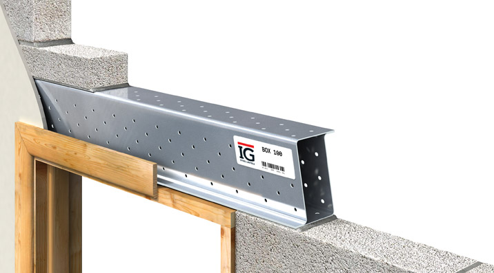
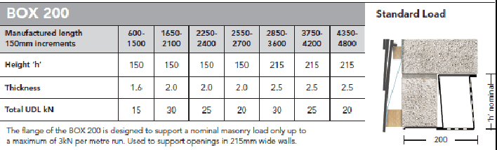
Box lintels can be used for internal or external openings and with a variation of wall thicknesses. The IG box lintel has perforations along its length acting as a plaster key. As an optional extra IG box lintels can be insulated.
The IG box lintel is designed to carry the full load of wet masonry as soon as it is installed.
Material
Box lintels are manufactured from pre-galvanised mild steel BS EN 10346:2009 DX51D plus Z600 or grade Z275 to BS5977: part 2, 1983 (BS EN 845-2:2003). There is a minimum zinc coating of 600g/m² galvanising including both sides.
If stainless steel lintels are required IG utilise stainless steel grade 304 2b to BS EN 10088- part 2 Astm 240 (European Grade 1.4307).
Box lintels can be insulated with expanded polystyrene and conforms to BS 13163:2008.
HD BOX 200
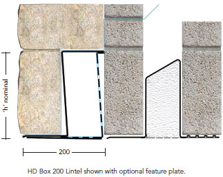
This drawing illustrates how a BOX 200 Lintel can be used tosupport a 215mm leaf of solid stonework on the outer face of a traditional cavity wall.
The three dimensional image also illustrates how a DPC/Cavity Tray should be installed with this detail.
NB: Cavity insulation omitted for clarity.